Patch Cabling
Straight-Through or Cross-Over
In general, the patch cords that you use with your Ethernet connections are "straight-through", which means that pin 1 of the plug on one end is connected to pin 1 of the plug on the other end.
Crossover cables are "crossed", end to end data cables aren't.
If you have a network hub that has an uplink port on it then you do not need to make (or purchase a cross-over cable). Just switch the port on the hub to the 'uplink' mode.
If your hub does not have an 'uplink' port on it then the only way to cascade another hub or attach a cable modem is to use a crossover cable.
For small jobs involving a pair of computers, or home wiring between two computers will not normally require a hub and you can use a crossover cable.
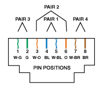
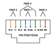
When wiring your own crossover cable to connect two PCs together, simply change ONE end of an ordinary RJ45 patch lead to that shown in following diagram.
It helps for future reference to mark or attach a tag to the crossover cable so that you do not attempt to use it as a 'normal' patch lead at some time in the future
RJ-45 Connectors - Patch Cables for Category 5 Wire
REMEMBER
- To hold the RJ45 connector with the 'clip' on the bottom.
- To have to the 'opening' (where you insert the cable) facing you.
| 258A RJ45 Jack (Jack face shown) |
258B RJ45 Jack (Jack face shown) |

|

|
Cross Over Patch Lead Pin to Pin Wiring
| PIN | RJ45 - 258A | PIN | RJ45 - T568A (T568B) | |||||||
|---|---|---|---|---|---|---|---|---|---|---|
| 1 | white/green | 1 | white/orange | |||||||
| 2 | green | 2 | orange | |||||||
| 3 | white/orange | 3 | white/green | |||||||
| 4 | blue | 4 | blue | |||||||
| 5 | white/blue | 5 | white/blue | |||||||
| 6 | orange | 6 | green | |||||||
| 7 | white/brown | 7 | white/brown/ | |||||||
| 8 | brown | 8 | brown | |||||||
Cross Over Pin to Pin
| Pin 1 Pin 2 Pin 3 Pin 4 Pin 5 Pin 6 Pin 7 Pin 8 |
to to to to to to to to |
Pin 3 Pin 6 Pin 1 Pin 4 Pin 5 Pin 2 Pin 7 Pin 8 |
||
|
Pins 4, 5, 7 and 8 remain the same
|
||||